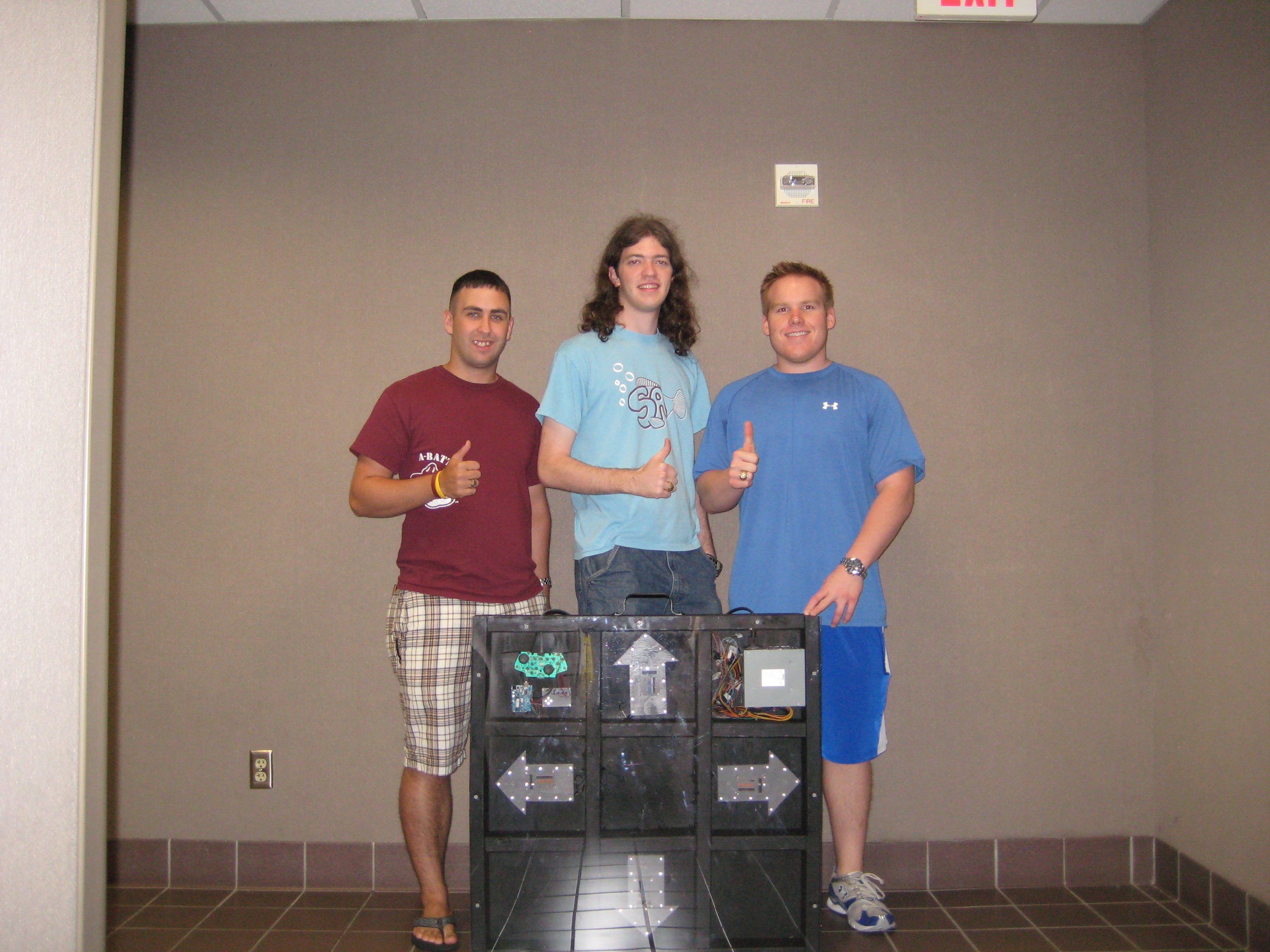
Pictured: William Somers, Drew Fisher, and William Bengtson
Project overview
This project was created for Dr. Steve Liu's CPSC462 (Microcomputer Systems) class at Texas A&M University.
Initially, we saw a neat paper by Mitsubishi Electric Research Laboratories on using LEDs as light sensors (Dietz, P.H.; Yerazunis, W.S.; Leigh, D.L., "Very Low Cost Sensing and Communication Using Bidirectional LEDS", International Conference on Ubiquitous Computing (UbiComp), October 2003). We decided we wanted to use this concept to implement something cool.
In this project, we designed, implemented, and constructed a DDR pad. A problem with most industrial designs is that over time, moving parts wear out and the pad no longer recognizes steps on a particular arrow. We designed our pad to have no moving parts. Instead, we chose to measure light reflectance off the user's feet to determine if one of the arrows was being stepped on or not.
Since a design with no moving parts offers little to no tactile feedback, we wanted to make sure the pad offered some other form of feedback, so the user would know when they had successfully stepped on the arrow. To this end, we chose to embed LEDs in the arrows themselves, and to have them illuminate when the arrow was pressed. We also decided we'd like to have these LEDs flash in time with the music.
Design overview
The design consists of one master controller and four slave controllers. Each slave controls a set of 15 LEDs. Thirteen LEDs are placed around the border of the arrow and flash in rhythm with the music. The remaining two LEDs are used as an illumination and sensing pair - the LED pointing straight up acts as a permanent flashlight, and the LED at an angle serves to sense reflection of the previous LED off the foot of the player.
Readings are taken with the technique described in the MERL paper, summarized here. We place the interior sensing LED in reverse bias mode to allow the LED to charge up a capacitance in the LED junction itself. When a reading is to be taken, we set the cathode to input mode, disable the internal pull-up resistor, and time how long it takes the capacitance to discharge. Greater light input results in a shorter discharge time. As light from the illumination LED reflects off the foot of the player, the time the LED takes to discharge through the microcontroller decreases. By comparing this time to a threshold, the slaves determine if the arrow is pressed, and will raise or lower a line to the master accordingly.
The slaves can also read the voltage of a line from the master. When this bit is high, the slaves illuminate the arrow LEDs.
The master runs the main DDR pad controller program. It determines when the arrow LEDs should be on by and receives constant readings from the slaves. The master passes the readings from the slaves on to the Xbox 360 controller. The master can receive lighting commands from Stepmania running on a computer through a USB serial port, or it can just leech power from an Xbox 360.
Hardware design
The frame of the DDR pad was built using plywood and 2x4 pieces of wood to divide the pad into 9 equal squares in a 3x3 fashion. The bottom of the pad is a piece of plywood cut to 33"x33". The left and right edges were constructed using 33" pieces of 2x4 laid on their narrow side. The upper and bottom edges and the two horizontal dividing pieces were constructed with 30" pieces of 2x4 on their thin sides, so that they fit within the left and right edges. The vertical dividing pieces were constructed as 6 10" pieces of 2x4 on their thin sides to fit within the horizontal dividers. The 2x4 pieces of wood are screwed together at every meeting point and screwed into the plywood from the bottom. The four pieces that create the middle square had holes drilled in them before being screwed in, so that wires could pass underneath the 2x4. Similar treatment was given to the two horizontal dividing pieces of the top left and top right squares. 1" circular holes were drilled in the upper edge in the center of the top left and top right squares so communication and power cables could be run to the pad. After all holes were drilled and all the pieces were screwed together, the frame as a whole was spray painted with one coat of primer and two coats of black paint.
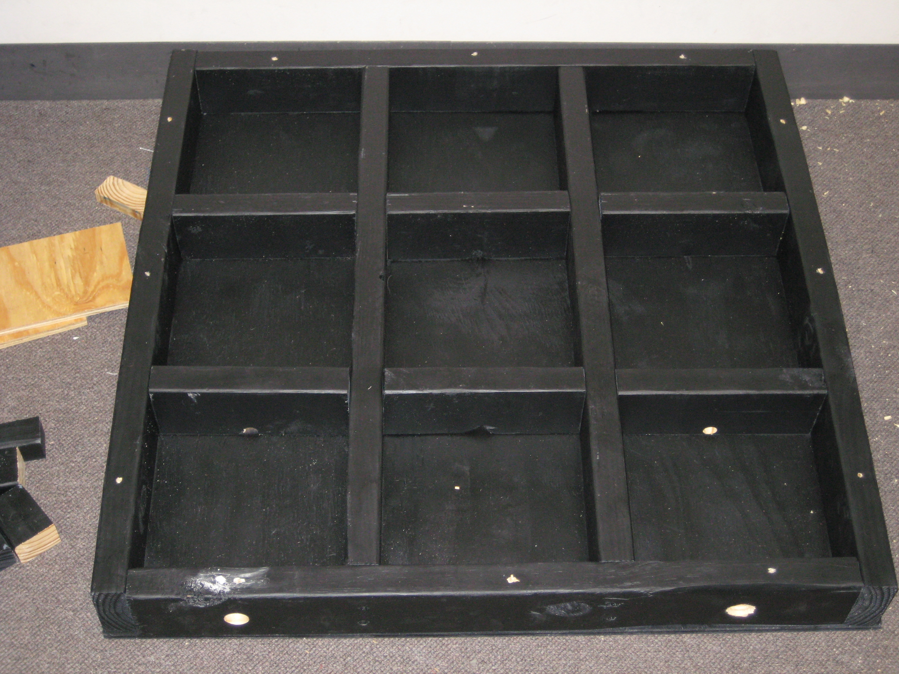
Frame of the wood base.
The top of the DDR pad was constructed using a 1/4" thick 33"x33" sheet of Lexan screwed to the four edges of the frame with twelve screws. A large heavy duty black handle was attached to center of the top edge.

Adding the handle.
The four arrows of the DDR pad were constructed out of the same plywood as the base of the pad. They were cut into the shape of arrows about 8" long and 4" wide at the base. 13 holes were drilled around the edge of the arrow for the LED leads to fit through, and a 1" circular hole was drilled in the center for all wires of the slave board to pass through.
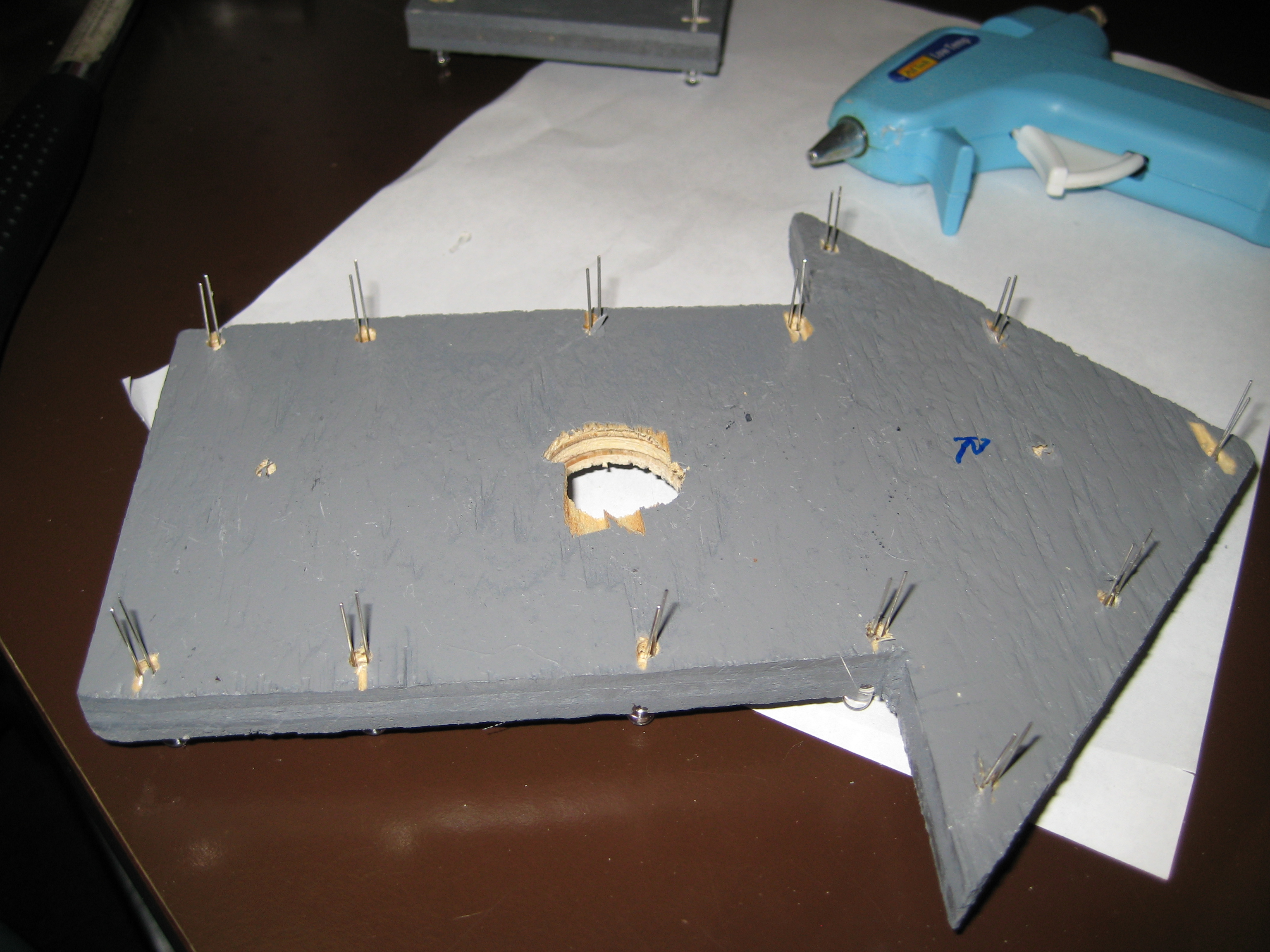
The underside of an arrow, before connecting leads.
The supporting pieces of the arrows were constructed out of four 2"x2" plywood squares; two stacked together each for the point and for the base of the arrow. The arrows were attached to the supporting posts with one screw from the top of the arrow and the posts were attached to the bottom of the frame with one screw from the bottom of the frame (through the plywood base). Before the pieces were assembled, they were painted. We applied one coat of primer to all the pieces, then painted the arrow with two coats of granite colored paint and the supporting square posts with two coats of black paint.

Adjusting wires. Note that each arrow has four connctors: power, ground, data from master, and data to master.
The Xbox 360 controller board was mounted in the top left square, along with the master chip (in the Aurduino development board), and the master board (with hardware used to interface the master chip and Xbox 360 controller board). The Xbox 360 controller was mounted on two 2"x2" pieces of 2x4 spray painted black and screwed into the bottom of the frame. The master chip was screwed onto 1" metal risers and hot glued to the bottom of the DDR frame. The master breakout was screwed onto 1/2" risers and hot glued to the bottom of the frame. A Dell desktop computer power supply was mounted in the top right square by screwing it to the right edge of the frame. All four slave boards were screwed onto 1/2" risers and hot glued to the top of the arrow above the 1" circular hole. All wires throughout the pad were either hot glued out of sight or hot glued to an edge and spray painted black.
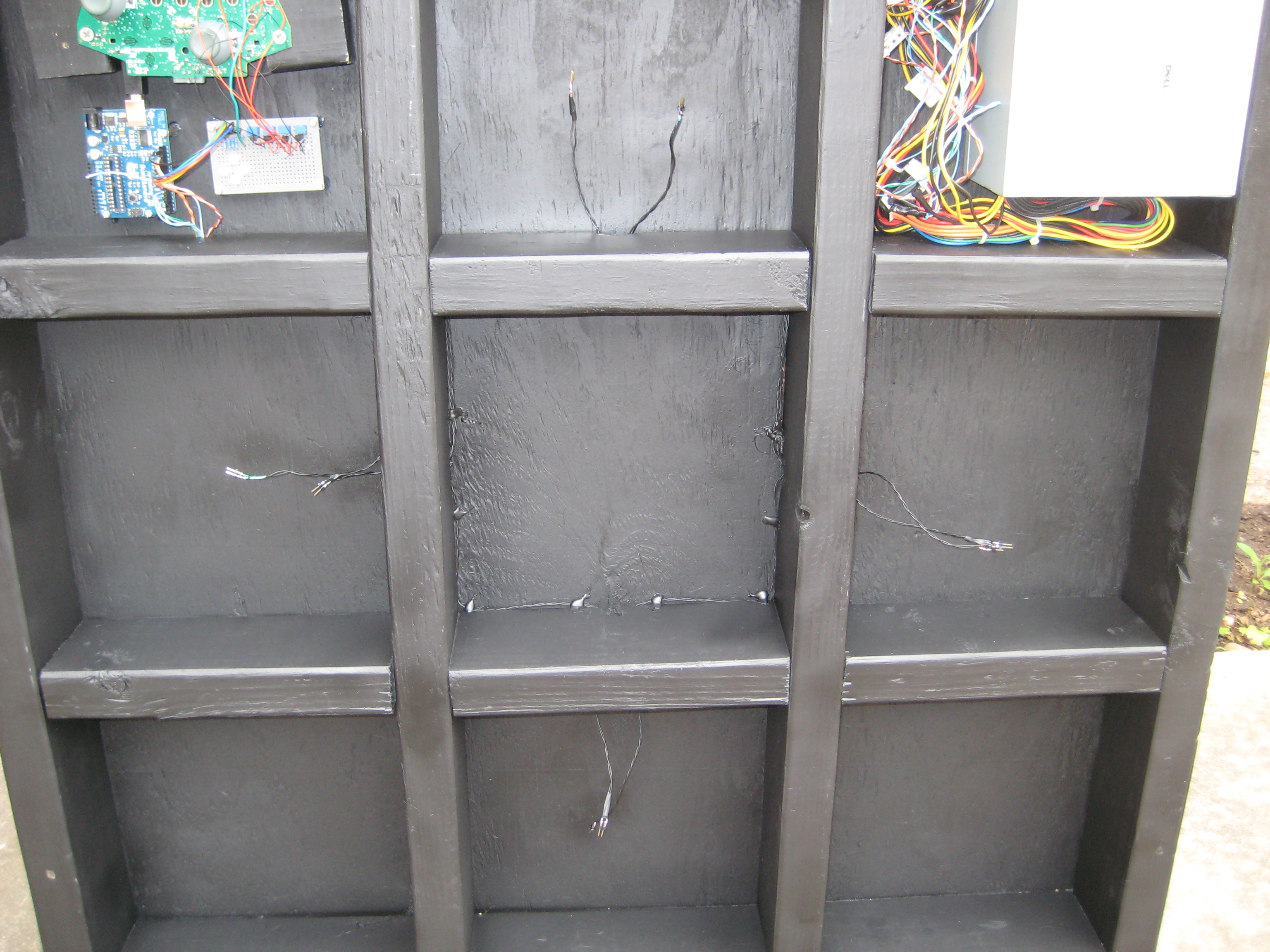
The board with power suppply, master board, Xbox 360 controller, and cables run inside.
Electronics design
Our electronics design consists of 4 slave boards located on each arrow and 1 master board that serves as the interface between the slave boards, the computer, and the Xbox360 controller. These slave boards each held an ATmega328P microcontroller, one 20 MHz resonator with internal capacitors, two ULN2004A LED drivers and 15 LEDs. A main design was used for all the slave boards. The only difference between the two slave board designs (one for blue LEDs, the other for red LEDs) are the resistors used in series with the LEDs to prevent them from passing too much current.
We calculated that, to keep current through the LEDs below 20mA (well within their maximum rating), we would need 50 Ohm resistors for the blue LEDs and 115 Ohm resistors for the red LEDs. Each slave board used two blue LEDs for sensing: one LED is kept constantly lit while the other is polled to detect light reflection.
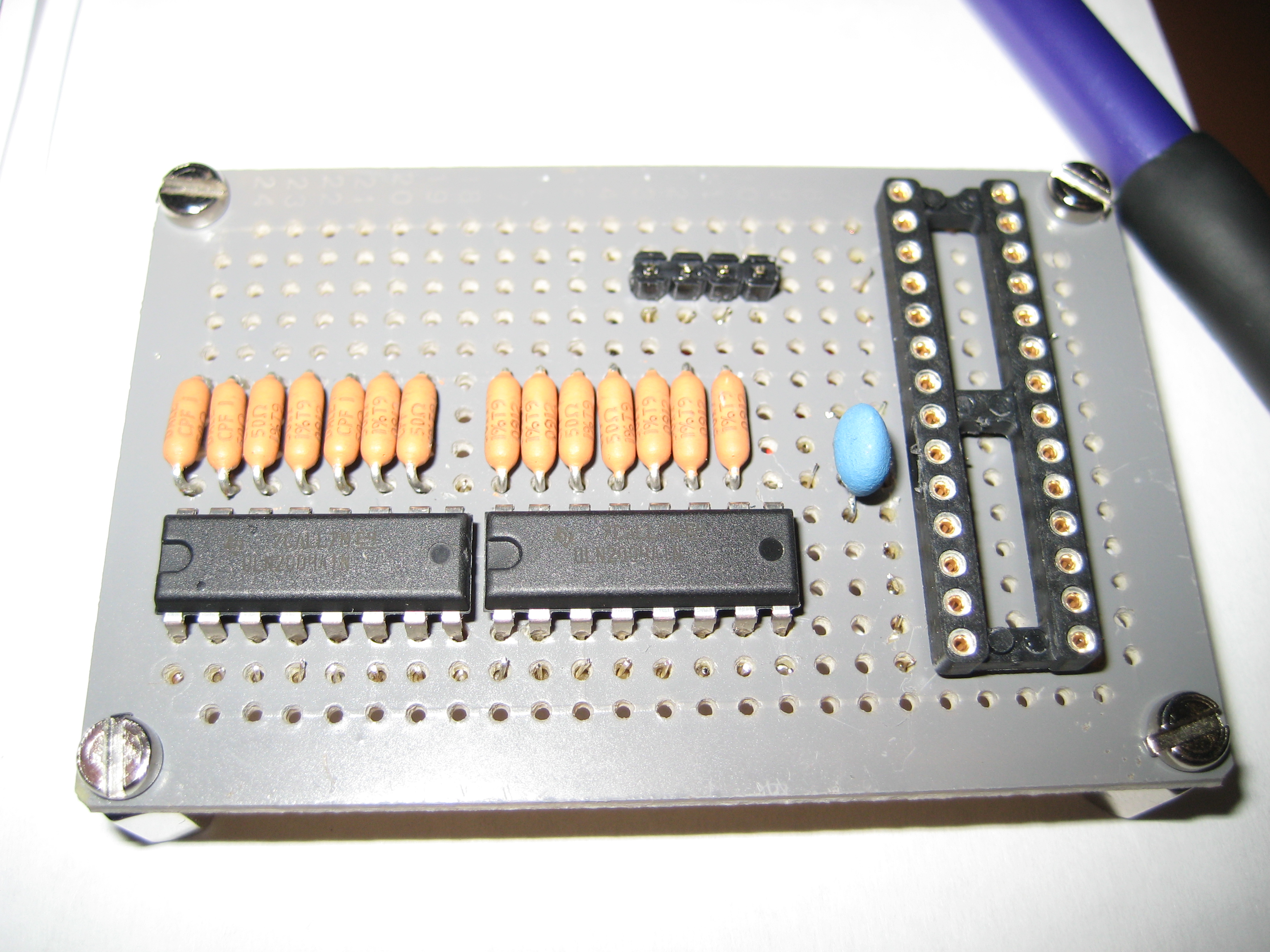
Close-up of the slave board.
Each driver is connected to VCC and GND. The drivers act as an open circuit when the pin from the ATmega328 is low. When said pin goes high, the circuit closes which allows the LED to turn on. Each LED, excluding the sensing LED, has the cathode tied to VCC and the anode tied to the LED driver.
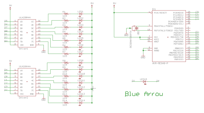
The blue slave board schematic shows the pin configurations on the ATmega328P microcontroller, their connections to the LED drivers and the use of the 50 Ohm resistors.
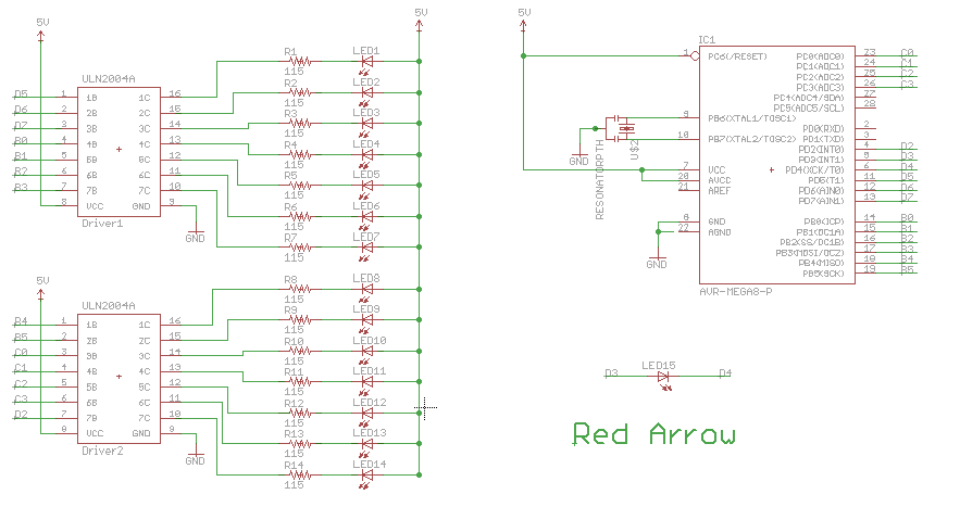
The red slave board schematic shows the pin configurations on the ATmega328P microcontroller, their connections to the LED drivers and the use of the 115 Ohm resistors.
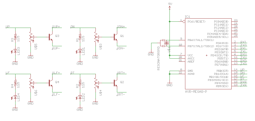
The master board schematic shows the pin configurations on the ATmega328P microcontroller, their communications to the slaves, and the communication to the Xbox 360 controller. Ordinarily, when a user presses a button on the Xbox 360 controller, it completes a circuit through a resistive pad. To emulate this, we have a transistor tied to the two sides of the resistive pads and connect the base to a pin from the master board. We use potentiometers as voltage dividers to adjust the voltage applied at the base to prevent over-volting the Xbox 360 controller. We raise a pin on the master board, the transistor activates, current flows, and the Xbox 360 controller thinks the button is pressed.
In parallel with this circuit we have an LED and current-limiting resistor to indicate to the user that their foot step is being registered. The whole Xbox 360 button control circuit is seen four times on our master board to accomodate the four arrows: up, down, right, and left.
Software design
The software portion of this project consists of three important parts:- "Master" microcontroller code
- "Slave" microcontroller code
- Computer game code
Master microcontroller code
Part 1 is implemented as a simple infinite loop that samples the four input lines from the four slaves and writes matching values to the output lines to the Xbox360 controller. It also listens for serial commands - when it receives a '1' character, it will raise the four output lines to the four slaves to a digital HIGH, and it will drop them upon receipt of a '0'. The slaves, in turn, will see the line go high and illuminate the LEDs in the arrow.
Slave microcontroller code
Part 2 is a bit more complex. Each slave arrow has fourteen separately controllable LEDs on 14 different pins, and one LED that acts as a sensor taking up two pins.
Sensing involves applying a reverse bias to the sensing LED to charge the LED's internal capacitance, then swapping the anode to input mode and disables the internal pullup resistor. It then counts the number of times it goes through a busy loop before the anode reads a logical low again. The more light the LED receives, the lower the number of loops.
To ensure that the arrow responds promptly to changes in the line from the master indicating light data, each iteration through the busy loop checks the status of that pin, and updates the LEDs accordingly.
We experimented with different loop counts to determine a threshold below which our code assumes that a foot is present and above which our code assumes the foot is absent. We thus go through the busy loop this threshold number of times - if the anode input hasn't gone low yet, we assume no foot is present and begin a new sample. This allows us to keep a fast sample rate, which is important for a rhythm game like DDR.
Our current code will illuminate all the LEDs in the arrow when:
- The last sample of the sensing LED went low before threshold iterations (the button is "pressed"), or
- The master has indicated that the lights should be illuminated by raising that pin to logical high.
Since each LED can be individually controlled, it is possible to reprogram the atmega328 chips to display various patterns. Getting consistent timings may be difficult, due to the nature of the variable speed at which the slaves sample (since reading a low value takes less time than reading a high one). Such code has not been implemented yet, but would require no hardware changes to effect.
Computer game code
Part 3 consists of modifications to an existing open-source program, Stepmania to send light data to our master microcontroller. Stepmania already has support for the use of standard joysticks as input devices, so by using a USB HID device (like the Xbox360 controller), we did not have to modify any code to make Stepmania recognize our pad as an input device.
Our software development was done on Linux machines, but we also wanted to ensure that the DDR pad could be used on Windows machines as well. To this end, we implemented the serial-port lighting control for both platforms.
Since we were unsure what COM port the master board would appear as to the Windows systems, we also added a commandline switch to allow the user to specify which serial port Stepmania should use to send lighting data. Invoking Stepmania in the following manner will tell the program to send light data to COM10:
Stepmania.exe --serialport=COM10
If Stepmania is unable to open the appropriate serial port, it will simply continue running without sending any lighting data to the pad, and will continue to function with the pad as an input device.
As Stepmania is open-source and distributed under the GNU GPL, we have provided our patches which apply against SVN r28063 at the time of writing (2009-05-10).
Challenges faced
While the project has come together into a successful product, we experienced many trials along the way. This document serves to exhibit some of our failures, how we discovered them, and how we resolved them.Challenge 1
We discovered that the use of the LEDs as sensors was sensitive to wire length. Specifically, we found that six inches of 22-gauge wire had substantially more capacitance to charge and discharge than that of the LEDs that we were trying to measure. The signal-to-noise ratio, as measured with a multimeter, was about 1 to 20. This meant that we would have to use minimal wire to connect the sensing LEDs, which meant we'd need a microcontroller next to each sensing LED. As such, it became infeasible to have as many sensing LEDs as we had originally hoped for.
While we toyed with the thought of calibrating the wire lengths to serve as antennae, which would change capacitance depending on proximity of the player, the difficulty in implementing such an idea put it out of our consideration.
Challenge 2
We were trying to create a breakout board on which to test the ATmega328 chips, as we would be needing them for the slave boards (which we needed because any significant length of wire would ruin our light readings). We failed to realize that the RESET pin (Pin 1) needed to be tied to 5V for the chip to operate properly. As we left that pin floating, the chip remained in a constant state of RESET, which meant that it wasn't doing much useful.
We also failed to attach a crystal resonator to the ATmega328s, which, compounded with the aforementioned problem, rendered the breakout boards fully nonresponsive. After rereading the spec sheets and reviewing the Arduino board schematics, we discovered our errors, and purchased the appropriate crystals and connected Pin 1 to power. Now our breakout boards would execute code and blink an LED.
Challenge 3
We tried communicating with the slave boards via a serial port with a RS232 shifter to convert TTL voltage levels to those of RS232. Unfortunately, the data came through all wrong - an ASCII 'A' (0b01000001) came out as an ASCII 'Á' (0b11000001). It seemed that the timings were close, but slightly off. We realized that this was because the UART delays were calibrated for a 16MHz crystal clock, rather than the 20MHz crystals we were using. A one-line change in the Arduino dev environment configuration, and we had correctly-functioning serial communications again.
Challenge 4
We purchased a sheet of 1/8th inch polycarbonate. It proved too flimsy, so we wound up having to purchase a 1/4th inch sheet, to the tune of 125 dollars. Now it's pretty, although polycarbonate scratches rather easily. We decided that players will be required to wear socks while using our pad, to ensure its longevity.
Challenge 5
After we finished constructing all of the slave boards, we connected them all to the master, and tried to power them up. Some of the boards wouldn't power on. It turns out that we were trying to pull too much current from the power supply on the same pins, and the PSU couldn't handle that kind of sudden draw. By rewiring our connections to use different PSU pins, we got all the slaves to power on properly together.
Challenge 6
Once we had all the arrows connected, and the slaves communicating successfully with the master, we discovered that our slaves sampled somewhat slowly and would not blink in time together. This was because a single sample of the sensing LEDs could take a quarter of a second if said LED had little illumination. Since the software only updated the arrow LEDs in between samples, if the state of the master TX pin changed during a sample, that slave would not update the lights until the end of that sample. This was resolved by having the slaves update the lights constantly during the sample-collection period, and adjusting the threshold constants accordingly. This resolved our last major problem.
Future Improvements
While this project did successfully implement our original goals, there is still room for further development.
One improvement would be to fabricate Printed Circuit Boards (PCBs) in the shape of arrows to allow for more uniform design and additional sensing LEDs within each square. This would provide greater reliability and a larger sensing surface.
A second improvement we might make would be to improve the light sensing routine to take more uniform time, or perhaps even drop the LED-as-sensor idea and just use a normal photoresistor or phototransistor for greater sensitivity. We could also make improvements to the algorithm to make the sensor more robust to different light conditions and footwear.
Another improvement would be to have more complicated blinking patterns of the arrow LEDS. They could show a circular pattern, a pattern that turned the LEDs on in order from the base to the head of the arrow, and other random patterns.
Bill of Materials
| Item | Quantity | Price per unit | Total cost |
|---|---|---|---|
| Arduino Dev USB Board | 1 | $29.95 | $29.95 |
| RS-232 Shifter SMD | 1 | $13.95 | $13.95 |
| AVR 28pin 20MHz 32K-ATMega328 | 6 | $4.30 | $25.80 |
| Breakaway Female Headers | 3 | $1.50 | $4.50 |
| Breakaway Headers-Straight | 2 | $2.50 | $5.00 |
| 115 Ohm Resistor 1% | 30 | $0.05 | $1.50 |
| 50 Ohm Resistor 1% | 30 | $0.38 | $11.40 |
| ULN2004A LED Driver | 10 | $0.64 | $6.40 |
| 28 Pin IC Sockets | 5 | $2.01 | $10.05 |
| Single Turn Trimmer Pots 20KOhm | 5 | $0.75 | $3.75 |
| Small Signal Transistor | 4 | $0.08 | $0.32 |
| Wood, Lexan, Screws | ~$75.00 | $75.00 | |
| 1/8" 33" x 34" Lexan | 1 | $84.00 | $84.00 |
| 1/4" 33" x 34" Lexan | 1 | $120.00 | $120.00 |
| Total | $391.62 |